In HEC-RAS, lateral structures are used to model flow that exits a river and moves into a neighboring area—such as another stream, a 2D flow area, or a storage basin. They are an essential tool for simulating scenarios where water overtops the riverbanks and leaves the main channel. By default, HEC-RAS generates water surface profiles by assuming that water builds up vertically, without naturally accounting for overflow beyond the cross-section geometry. As a result, users need to manually add features like lateral structures to their 1D models to properly represent water leaving the system.
Lateral structures can simulate various real-world features, including levees, diversion channels, spillways, and even natural berms. While lateral structures are useful geometric elements, they can also introduce stability challenges into a HEC-RAS model if not configured carefully. The following article will discuss how to add lateral structures in HEC-RAS and share some tips for managing common stability issues that can arise when using them..
What is a lateral structure?
As previously mentioned, lateral structures are geometric elements in HEC-RAS that define how water flows laterally to the stream centerline. Lateral structures do not necessarily need to represent an actual structure. However, they are commonly used to model levees, diversion structures, spillways, or even natural berms. They can also be used to estimate the amount of water that overtops stream banks and enters an offline 2D area, storage area, or another stream. Alternatively, the user can allow water to leave the stream system and disappear into nowhere. However, it is worth noting that HEC-RAS will not be able to account for any submergence effects or tailwater when you simply allow flow into an abyss.
How does water pass over a lateral structure in HEC-RAS?
Water passes over a lateral structure from a 1D cross section into an adjacent area when the water surface elevation for a cross section exceeds the user-defined crest of the lateral structure. HEC-RAS does account for the fact that a lateral structure is a continuous surface with varying water surface elevations at each cross section by interpolating to determine whether the lateral structure is being overtopped between cross sections.
Adding a lateral structure in HEC-RAS
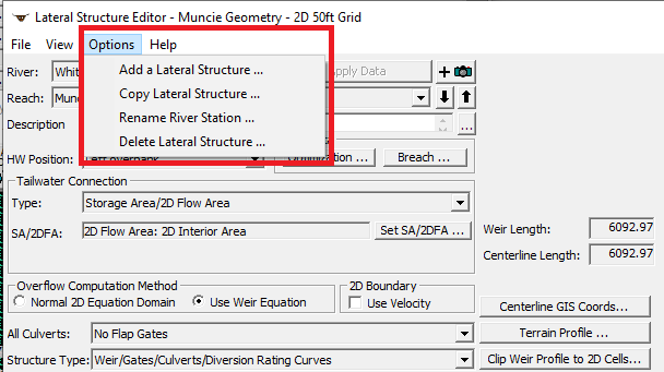
Users can add lateral structures in the Geometric Data Editor. Click the Lateral Structure button on the left side of the widow. Once the Lateral Structure Editor appears, select Options from the top menu and click Add Lateral Structure as shown in the image below.
Defining the location of a lateral structure
After clicking Add a Lateral Structure, HEC-RAS will ask for a river station. The river station can be any number between the two cross sections where a lateral structure will be located. HEC-RAS does not position the lateral structure based on the river station. The user-entered river station number simply shows which cross sections the lateral structure sits between.
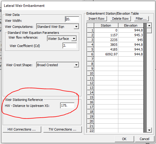
The position of a lateral structure is based on the user-defined parameters added to the Lateral Weir Embankment data editor. To define the headwater distance, click on the Weir/Embankment button within the Lateral Structure Editor. Under the Weir Stationing Reference section, you will see a box for HW – Distance to Upstream XS. The headwater distance to the upstream cross section is the distance between the cross section upstream of the lateral structure and the upstream end of the lateral structure itself.
After drawing your lateral structure, you can use the measure tool (hold down the CTRL key and click where you want to measure) to determine the headwater distance. The following section will discuss how to draw a lateral structure in the Geometric Data Editor.
Drawing your lateral structure
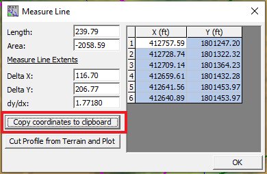
To draw your lateral structure in HEC-RAS, navigate to the Geometric Data Editor. Then hold down the CTRL button on your keyboard while drawing the path of the lateral structure. Next, copy the coordinates by clicking the Copy coordinates to clipboard button as shown below.
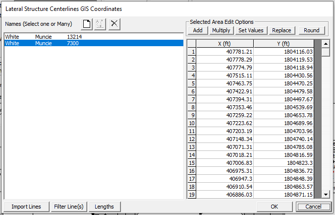
Finally, paste the coordinates into the Lateral Structure Centerlines GIS Coordinates dialog box located within the Lateral Structure Editor as shown below.
It is important to draw your lateral structures along high ground. This is particularly true when the flow on the “stream side” of that high ground is 1D and the flow on the “overbank side” of that high ground is 2D.
When developing a 1D/2D model, it is good practice to overlap the cross sections and the 2D flow area a little bit so there are no gaps in mapping. However, this overlap will cause HEC-RAS to double-count the storage in the system a little bit. However, this error should not be an issue if the overlap is not too significant. It is also worth noting that, computationally, HEC-RAS can still run with a gap between the edge of your cross sections and the boundary of the 2D flow area.
Finally, it is important to ensure that your weir length and the centerline length generated by the coordinates are the same. Otherwise, you will get an error.
How to define the crest of a lateral structure
After drawing the centerline of the lateral structure, you must define the crest. If you have high-quality terrain data, you can define the crest of your lateral structure using your terrain data. In this case, HEC-RAS will account for the fact that water may spill over your stream banks in one location and not in another location by allowing water to move into the cells that are adjacent to the lower crest elevations and not the cells adjacent to areas where the lateral structure is at a higher elevation. You can define the crest elevation of your lateral structure by clicking the Terrain Profile button in the Lateral Structure Editor. Then click on the Table tab and copy the two columns. Finally, paste this information into the Embankment Station/Elevation Table, which is accessed by clicking the Weir/Embankment button.
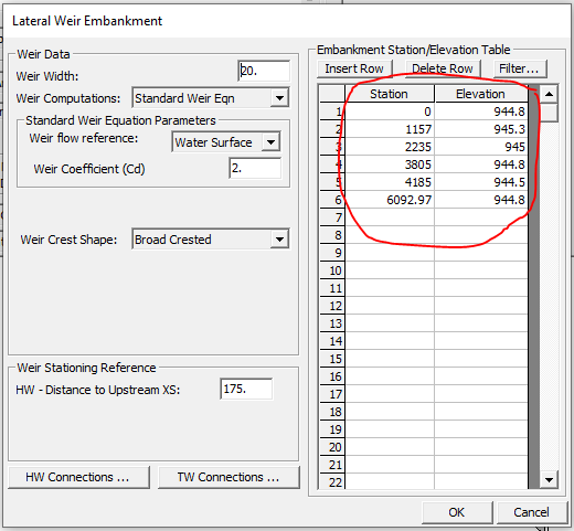
If you are defining a proposed levee or other structure, you can simply enter your own station/elevation information into the Embankment Station/Elevation Table.
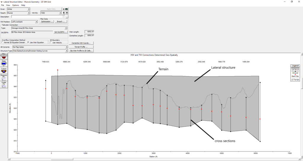
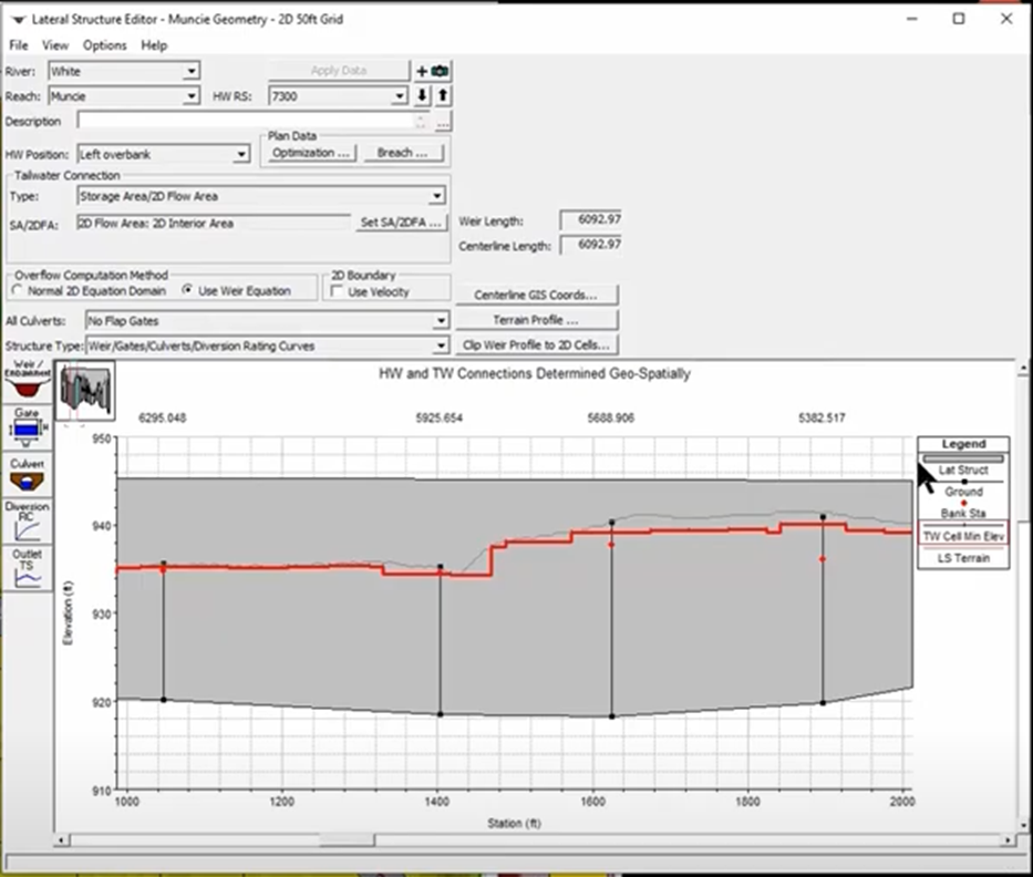
When defining a lateral structure that will convey flow from a stream to an offline 2D area, it is important to ensure that the crest of your lateral structure is higher than the minimum elevation of the adjacent cells. The line shown in red on the image below depicts the minimum elevation of the adjacent cells. If you are using the terrain to define the crest of your lateral structure, there are areas where the terrain is a bit too low. Luckily, in the newer versions of HEC-RAS, you can simply click the Clip Weir Profile to 2D Cells button to raise the crest elevation where necessary. This new feature is a time saver. In the past, users had to manually raise the crest elevation of the lateral structure based on (potentially) dozens of errors that would pop up when running the program.
Headwater Connections and Tailwater Connections
The weir stationing table, which can be accessed by clicking the Headwater Connections button in the Lateral Weir Embankment dialog box, defines where each HEC-RAS cross section is located along the lateral structure. This is because the reach associated with the lateral structure is the headwater side of the lateral structure. If your model is not georeferenced, this table will be populated based on either the left overbank, right overbank, or main channel reach distances (depending on which Headwater Position you select in the Lateral Structure Editor). For this reason, I recommend always starting with a georeferenced HEC-RAS model file.
A similar process is used to define the tailwater connections. Whatever you connect the lateral structure to (e.g., a 2D flow area, storage area, etc.) is the tailwater side of the lateral structure.
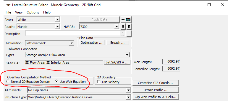
Overflow Computation Method
HEC-RAS allows the user to choose between two overflow computation methods for lateral structures: the weir equation and the normal 2D equation. The weir equation is the default option. However, the weir equation may not be the best choice when your lateral structure will be simply conveying overland flow from cross sections to a neighboring 2D flow area rather than directing flow over a raised surface/berm. HEC-RAS does have a “Zero Height” weir option for these types of situations. However, in these cases, the Normal 2D Equation Domain may be a better option. When you select this option, HEC-RAS uses the profile of the water surface along the lateral structure and uses the 2D equation to transfer water to the bounding cell faces.
Wier Coefficients
If you determine that the weir equation is more appropriate for your HEC-RAS model, you must enter a weir coefficient in the Lateral Weir Embankment dialog box. Many publications recommend lateral weir coefficients for “inline” situations, but there are not many resources applicable to lateral structures. Lateral weir coefficients should generally be much lower than their inline counterparts. This is because an inline structure will be more hydraulically efficient than a lateral weir. The default weir coefficient in HEC-RAS is 2, but Table 3-1 of the HEC-RAS 2D User’s Manual lists the range of appropriate weir coefficients for various situations. It should also be noted that when a lateral structure is used to represent the transfer of flow from a 1D river to a 2D Flow Area, the weir coefficients must be very low. Otherwise, excessive flow will be transferred over the lateral structure.
| What is being modeled with the lateral structure? | Description | Range of Weir Coefficients (English Units) |
| Levee/Roadway – 3 ft or higher above natural ground | Broad crested weir shape, flow over levee/road acts like weir flow. | 1.5 – 2.6 |
| Levee Roadway – 1 to 3 ft elevated above ground | Broad crested weir shape, flow over levee/road acts like weir flow, but becomes submerged easily. | 1.0 – 2.0 |
| Natural high ground barrier – 1 to 3 ft high | Does not really act like a weir, but water must flow over high ground to get into 2D flow area. Flow does not pass through critical depth. | 0.5 – 1.0 |
| Non-elevated overbank terrain. Lateral structure not elevated above ground. | Overland flow escaping the main river | 0.2 – 0.5 |
2D Boundary – Use Velocity
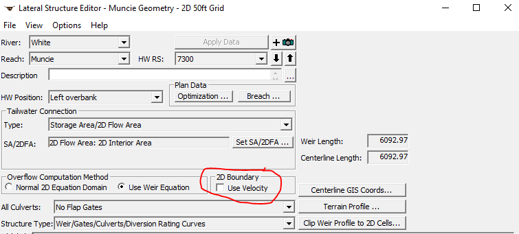
When the Use Velocity box is unchecked, HEC-RAS computes the volume of water that passes over the lateral structure. In other words, there is no momentum coming out of the 1D reach into the 2D flow area. In contrast, when the Use Velocity box is checked, HEC-RAS calculates a velocity over the cell faces adjacent to the lateral structure and will use that velocity to solve the momentum equations. This box, by default, is unchecked for stability purposes. However, I recommend running your final model with this box checked because it does increase the accuracy of your model results.
Connecting a 2D Flow Area to a 1D Reach With Lateral Structures
Sometimes, it makes sense for 2D flow areas to model areas behind levees or overbanks. Using a lateral structure, users can connect such 2D flow areas to the 1D reach. The following section will describe the general steps for adding a lateral structure to connect a 1D reach and a 2D flow area.
- Add the Lateral Structure in the same way as you would for a purely 1D HEC-RAS model following the steps described above.
- Select “Storage Area/2D Flow Area” as the Tailwater Connection option in the Lateral Structure Data Editor. Then select the 2D Flow Area of interest using the Set SA/2DFA button.
- Next, select the Weir/Embankment button on the left side of the Lateral Structure Data Editor. This will bring up an editor that allows the user to define the profile of the top of the embankment or levee.
- For the HW Connection to the 1D cross sections, the user can opt to use the default connection information. This information is generated by HEC-RAS, and this step is where georeferencing the lateral structure is helpful.
- Finally, the TW Connection button is used to link the 2D Flow Area Face Points to the Lateral Structure. Like the previous step, HEC-RAS will automatically determine the connections between the lateral structure and the 2D Flow Area. You may see negative values in the automatically generated table. This is because HEC-RAS will pick a Face Point just upstream of the lateral structure if the lateral structure does not start exactly at a 2D Flow Area Face Point to begin the connection. In other words, Station 0 of the lateral structure begins between 2 Face Points.
Note that if you change your 2D mesh, the numbering system for the HW and TW Connections will change. This could break the connection between your lateral structure and the 2D Flow Area. HEC-RAS will automatically reconnect the lateral structure to Face Points if you are using the RAS-computed intersections.
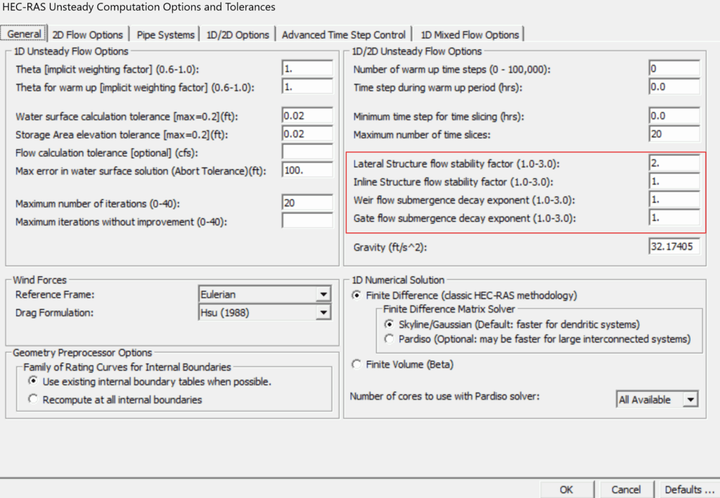
Submergence
Submergence over a weir is handled using submergence curves in HEC-RAS. The steep part of a submergence curve can cause instability. When there is a high degree of submergence as flow transfers from the upstream to the downstream side of a lateral structure, the downstream side of the lateral structure may end up with a higher water surface elevation than the upstream side. This causes flow from the downstream side to the upstream side of the lateral structure, resulting in oscillation. This can be fixed by increasing the submergence decay or adjusting the weir coefficient. A higher Weir Flow Submergence Decay Exponent will result in more stability. It should be noted that a flatter submergence curve (higher submergence decay exponent) may be a less accurate representation of how a weir behaves in real life. The trade-off is model stability.